Adding a Second Bypass Adapter to the 510/1100 Appliance Parent topic

When deploying Multi-Bridge mode or LACP-enabled configurations on your Deep Discovery Web Inspector appliance, the 
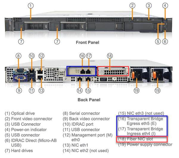
appliance configures data ingress/egress using the eth4/eth5 (bypass card 1), eth6/eth7 (bypass card 2) interfaces.
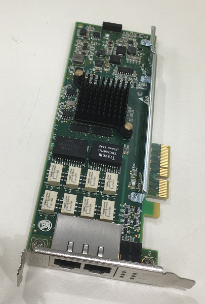
Deep Discovery Web Inspector 510/1100 uses an external NIC adapter (Silicom: Dual Port LAN Bypass Adapter (PE2G2BPI80) that is plugged into the first Fiber NIC slot (labeled as 16, 17 below) to support Bridge Mode and bypass mode. To deploy Multi-Bridge or LACP-enabled deployments, you must plug a second Dual Port LAN Bypass Adapter into your appliance using the second Fiber NIC slot (18).
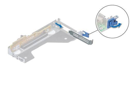
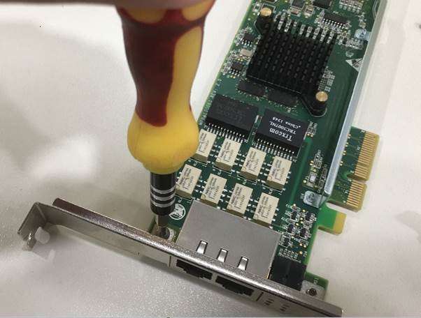
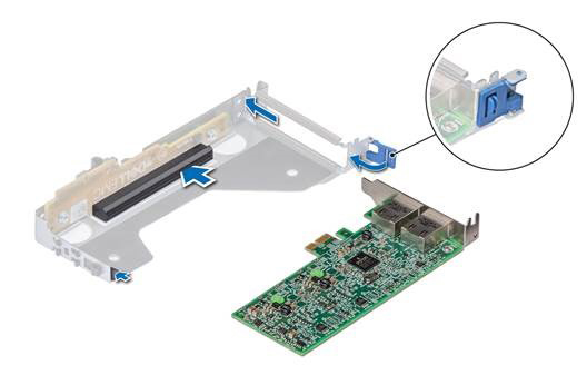
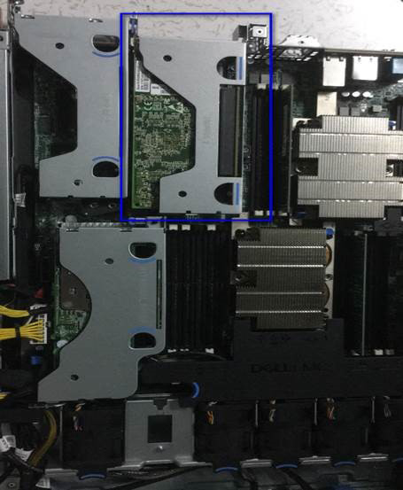
Use the following procedure to insert the second bypass adapter into the appliance.

Procedure

  1. Identify the location of the empty Fiber NIC slot (18) using the following diagram:
    ddwi_with_2nd_bypass.jpg
  2. Open the package and inspect the Silicom Dual Port LAN Bypass Adapter.
    The model and specification are at the following link: Silicom Dual Port LAN Bypass Adapter (PE2G2BPI80) specifications
    P/N Description Notes
    PE2G2PBI80-SD-R Dual Port Copper Gigabit PCI Ethernet PCI Express Bypass Server Adapter x4, Based on Intel 82580DB, PCI-E Gen 2.0, RoHS compliant
  3. Add the Dual Port LAN Bypass Adapter using the Fiber NIC slot.
    1. Perform a system shut down by pressing the Deep Discovery Web Inspector 510/1100 appliance's power button.
      ddwi_closeup_power_b.jpg
    2. Disconnect the appliance from the power supplies.
    3. Open the appliance chassis and pull the PCIe adapter holder latch, then remove the filler bracket.
      ddwi_pull_pcie_card_.jpg
    4. Replace the standard adapter riser with the provided low-profile riser using the following images for guidance.
      The Deep Discovery Web Inspector 510/1100 appliance supports only a low profile PCI adapter riser (also known as LPPCI or half-height adapters), but the Silicom Dual Port LAN Bypass Adapter is a standard (full height) PCI adapter by default. So you must replace the bracket on the LAN Bypass Adapter with the low-profile riser.
      bypass_card_replace_.jpg
      bypass_card_low_stan.jpg
      bypass_card_with_low.png
    5. Hold the adapter by its edges and align the adapter edge connector with the adapter connector on the riser. Insert the adapter edge connector firmly into the adapter connector until the adapter is fully seated. Then close the adapter retention latch.
      bypass_card_insert_i.jpg
    6. Fix the adapter holder latch into the appliance's chassis.
      ddwi_with_pcie_card_.jpg
    7. Close the appliance chassis and power on the machine.
      The LED per port of the bypass adapter turns on bypass (green), which means the bypass adapters are inserted correctly.
      ddwi_closeup_bypass_.jpg